MC4 Connectors: The Joint That Outlives the Panel
A connector joint does the hardest work on the array: it holds a current-carrying contact inside a gasket that must stay dry for the life of the plant. KUKA CABLE publishes MC4 / solar connectors, solar fuse connectors, solar diode connectors and PV cable assemblies as one range, and the cable that range sits on is rated DC 1.8/1.8 kV. The joint is only as good as the two parts either side of it, and the published cable data starts at an ambient window of −40 °C to +90 °C.
Key takeaways
- The range covers MC4 / solar connectors, solar fuse connectors, solar diode connectors and PV cable assemblies.
- The cable behind the joint is rated DC 1.8/1.8 kV, with a 10 kV spark test in production and a 6.5 kV AC, 50 Hz proof test for five minutes.
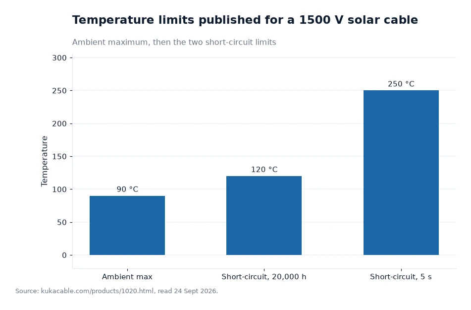
- Published temperature limits for the 1500 V cable are −40 °C to +90 °C ambient, +120 °C for 20,000 hours and +250 °C for five seconds.
- Certification is described as a starting point: certified cable is expected to hold its electrical performance for more than 25 years.
What the manufacturer publishes about the joint
The parts list is short and specific. KUKA CABLE names MC4 / solar connectors, solar fuse connectors, solar diode connectors and PV cable assemblies, and one solar cable connector page carries a CE / RoHS certificate download. Those parts are supplied with cable from the manufacturer's PV cable range whose published construction is a tinned copper conductor, class 5 flexible according to IEC 60228, inside electron-beam cross-linked XLPO insulation and sheath.
What is not published is just as useful to know. The site gives no connector temperature rating, no contact-resistance figure and no mating-cycle figure. Where a designer needs those, they come from the connector maker's own document, and the manufacturer's published role is the cable side of the pair.
Three decisions made before the connector closes
Stripping depth comes first. The published build for the 1.5 mm² to 10 mm² sizes uses 0.7 mm of insulation and 0.8 mm of sheath, and the stripped length should match the terminal's own depth so no bare strand sits outside the contact.
The crimp tool comes second. A class 5 conductor of 84 strands in 0.29 mm, as published for 6 mm², needs a die sized for the contact, not for the cable, and the tool's own data sheet is the only place that dimension is stated.
Torque comes third. The manufacturer publishes no torque value, so the figure on the mating pair's installation sheet is the one to use, with a torque driver rather than a spanner and a judgement. A joint that has been tightened twice to two different values is a joint that will be revisited.
Heat: the cable window sets the ceiling
The published temperature limits for the 1500 V solar cable are −40 °C to +90 °C ambient, +120 °C for 20,000 hours and +250 °C for five seconds under short-circuit. Those are cable figures. They matter here because a joint is a thermal series: a contact that runs warm puts heat into the insulation around it, and the insulation's own published allowance is the boundary of that chain.
Two of the three numbers apply to normal service rather than a fault. A roof surface in summer is well inside the +90 °C ambient limit, while the +120 °C figure describes the conductor temperature the cable is published to withstand continuously for 20,000 hours, which is a little over two years of running time.
Water, UV and the two ratings that appear in the material
The manufacturer lists a CPR fire rating and an AD8 waterproofing rating among the requirements it addresses for installations where those apply. Both describe the assembly rather than the connector alone, which is why the gasket at each joint matters as much as the contact inside it.
Sunlight arrives at the joint from two directions: directly on the connector body, and through the sheath along the run. The 1500 V solar cable page is where the temperature figures above come from, and the manufacturer's published UV work includes a 2,000-hour xenon lamp test, equivalent to about 360 weathering cycles, arranged on its solar cables to simulate intense sunlight, humidity and ozone.
Checking a delivered assembly
The published standards for the construction behind the joint are TUV 2PfG 1169/08.2007, EN 50618:2014 and IEC 62930. The speciality cable laboratory has run since December 2015 and is described as an ISO/IEC 17025 laboratory. Its quality framework, called the SIF quality model, includes 100% inspection of finished products for electrical, mechanical and environmental performance, plus retained samples for traceability. The certificates page holds the certificates that go with that inspection; ask for the copy matching the batch reference.
Ask for the batch reference on arrival and keep it with the as-built drawing. If a joint later runs warm, the retained sample and the test record turn the question into a comparison rather than a guess.
| Published parameter | Value as published | Where it appears |
|---|---|---|
| Rated voltage | DC 1.8/1.8 kV | 1500 V solar cable page |
| Spark test in production | 10 kV | 1500 V solar cable page |
| Proof test on finished cable | 6.5 kV AC, 50 Hz, 5 minutes | 1500 V solar cable page |
| Ambient temperature window | −40 °C to +90 °C | 1500 V solar cable page |
| Short-circuit, 20,000 hours | +120 °C | 1500 V solar cable page |
| Short-circuit, 5 seconds | +250 °C | 1500 V solar cable page |
Worked example
Work out how much heat a contact can add. A string carrying 9 A through a contact with 1 mΩ of contact resistance dissipates 9² × 0.001 = 0.081 W at that point — the author's own calculation, using the standard I²R relation and an assumed contact resistance, since the manufacturer publishes no contact-resistance figure.
Now place it against the published window. The cable's ambient limit is +90 °C and its 20,000-hour conductor limit is +120 °C, a margin of 30 °C by the author's subtraction. A poor crimp raising local resistance to 10 mΩ would dissipate 9² × 0.010 = 0.81 W in that joint instead of 0.081 W, ten times the figure, which is the reason the interface drawing and the crimp die are worth checking before installation rather than after a thermal survey.
Frequently asked questions
Do MC4 connectors have to come from the same brand as the cable?
The manufacturer publishes MC4 / solar connectors, solar fuse connectors, solar diode connectors and PV cable assemblies as one range, on cable rated DC 1.8/1.8 kV. The site does not publish a cross-mating statement, so the practical route is to order the connector pair and the cable together from the same range, then check the gland's stated working range against the diameter printed on the reel.
What temperature can a mated joint see in service?
The published temperature limits are for the 1500 V solar cable rather than the connector: −40 °C to +90 °C ambient, +120 °C for 20,000 hours and +250 °C for five seconds under short-circuit. Those cable figures set the ceiling the joint works under, because the contact and the insulation around it share the same thermal path.
What to ask for with the next connector order
Ask for the pairing document that states the crimp die, the stripped length and the torque for the contact being bought, and check the reel's printed outer diameter against the gland's stated range before any joint is closed. Ask for the batch reference so the retained sample at the factory can be traced. The published cable data to match against the pair is short: DC 1.8/1.8 kV, the 10 kV spark test in production and the 6.5 kV AC, 50 Hz proof test for five minutes. The manufacturer publishes no price, MOQ or lead time, so those belong in the enquiry.
Cable data used beside the connector notes above is the manufacturer's own website material, gathered with a 24 Sept 2026 read date[1].